Assignments
Group Assignment- characterize the features of the lasercutters including focus, power, speed, frequency and kerf for different materials
Week 3
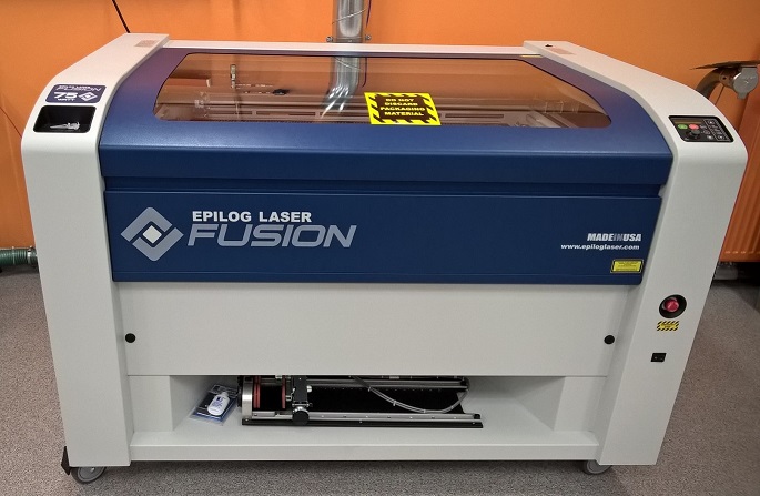
Figure 1. Epilog Fusion M2 40 Laser
In the laser cutter control panel, there are different features as following:To have a good understanding of the machine features, our instructor (Behnaz) had prepared some simple design with different settings including Focus modes (Figure 2a) and Speed, dpi and Power modes (Figure 2b) using MDF with 3mm thickness as the selected material.
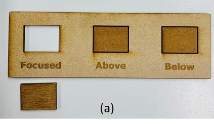
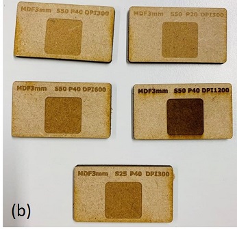
Figure 2. Printed different modes of (a) Focus, (b) Speed, dpi and Power with MDF.
As it can be seen in Figure 2a, the wrong focus can affect the engraving quality. With the same speed and resolution, increasing the power can increase the quality of engraving while decreasing the speed (with keeping the power and dpi constant) can have similar effect. Also, increasing the dpi clearly increases the quaility of engraving but too much dpi can also have a negative effect on it.
There are three different options in printing setting: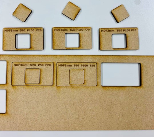
Figure 3. Testing vector (cut parts) and raster (engraved characters) modes with MDF
According to the results, increasing the frequency did not affect the quality, significantly. Increasing speed and power at the same time did not have a good effect and left the vector part uncut. So, to have a successful raster or vector proccess, you should decrease one of these parameters, while increase the other. For example in vector process, if it does not cut through, we can increase the power and decrease the speed and try it again.
In the advanced setting, you can even choose the material for printing.
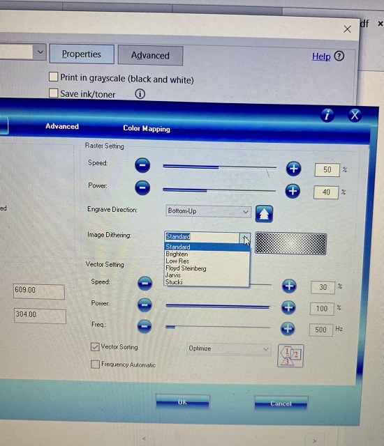
Figure 4. Different modes of setting
We printed the MDF material with all of different settings and then, measure the slots to figure out of the difference (Figure 5c) and discuss together to calculate kerf.
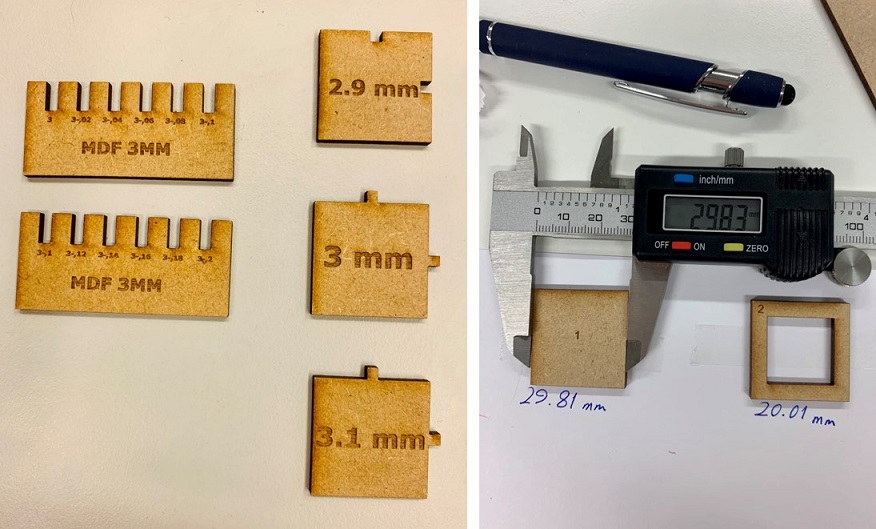
Figure 5. Printed different values of kerf (left) and measuring the printed components slots to calculate the kerf (right).
According to our measurements and my undestaring, the general formula for defining slot and tab is as the following:
To convert a raster image into vector with Inkscape, I used, this tutorial and performed the following steps:
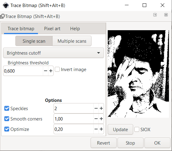
Figure 6. Trace Bitmap in Inkspace\choosing filter
Since the selected photos had many details and the separating lines between the areas where not clear, I decided to change it to another design for this week assignment but will be back to work on it later. Therefore, I opened the vectorized image of my granny in Inkspace which I made it at the second week with GIMP and performed the following steps:
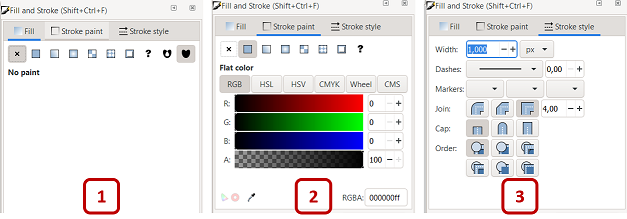
Figure 7. Preparing the image for vinyl cutting in Inkspace
It is advised to create a frame around the image, to ease the peeling of the cut design.
After preparing the design in Inkspace, I started to work with the vinyl cutter in Fablab Oulu which is Roland CAMM-1 GS-24 (Figure 8).
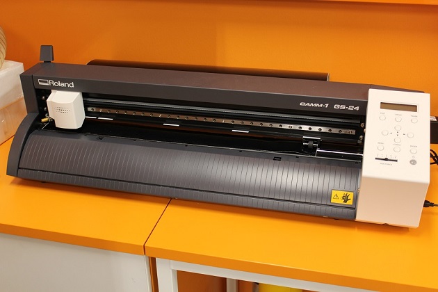
Figure 8. Roland CAMM-1 GS-24 vinyl cutter
The basic steps for using the vinyl cutter are as the following: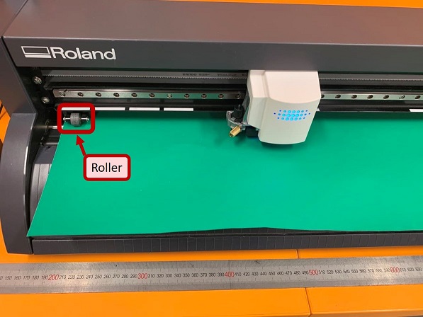
Figure 9. Adjust the roll with roller in Roland CAMM-1 GS-24 vinyl cutter
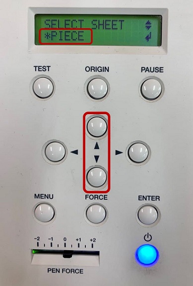
Figure 10. Roland CAMM-1 GS-24 control panel for choosing the material
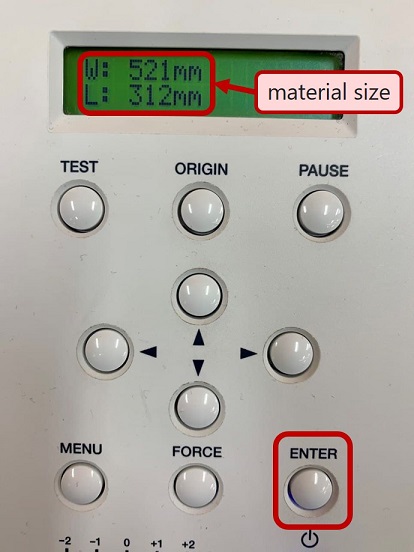
Figure 11. Initiating of the automatic measurement of the material size in Roland CAMM-1 GS-24 control panel
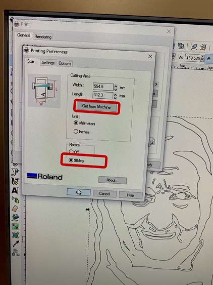
Figure 12. Printing settings for vinyl cutter
When cutting was finished, I removed the material from the machine and with a tweezer and tried to peel the unwanted parts. Unexpectedly, this part was a bit tricky because of very small traced areas of the image (wrinkles). Then, I realized it would be better to choose an image with clear and distinguishable tracing lines. After peeling the sticker, I sticked it to an oil paper and put it in a frame. Well, I really liked the result! Hope granny also like it from up there😊.
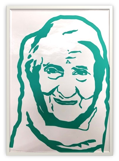
Figure 13. Final result of vinyl cutting
For the press fit construction kit, I checked the past projects of the former students to get some ideas. Since I was a beginner in Fusion 360 and I knew thar measuring kerf and cutting can be tricky and very time-consuming, I ended up with a ball shape made by hexagons connected with a joint. I had some struggles making 2D design in Fusion 360 which I will explain here.
First, I started to simply draw a hexagon (Sketch->Line). Then, for making the slots, I drew rectangles (Sketch->2-Point Rectangle) and tried to put them at the same line of each side manually (Figure 10). Next, I cut the extra lines through Modify->Trim . I also defined the parameters after drawing the first sketch which made trouble since it was not possible to assign the defined parameters to the side I desired. So, I found first of all, I should define the parameters. For assigning values to the design, I went to Sketch Dimension.
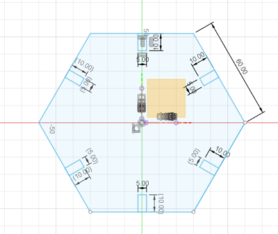
Figure 14. Drawing sketches and adding rectangles as the slots
That was not a good idea since for 3D design and after extruding, I noticed some extra lines (circled area in Figure 15).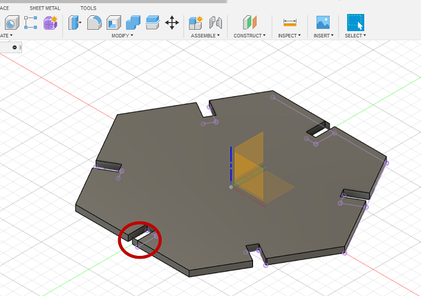
Figure 15. 3D design of the Figure 10 with unwanted areas
Therefore, I went to Modify>>Change parameters and after discussing the sizes with Behnaz, I defined the parameters as the following: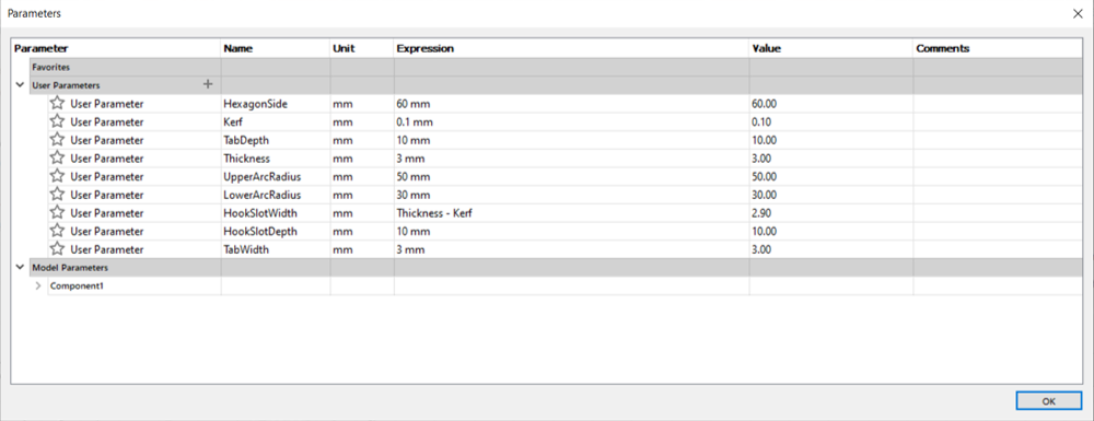
Figure 16. Defining parameters
Figure 13 shows the defined parameters on the sketches in Fusion 360.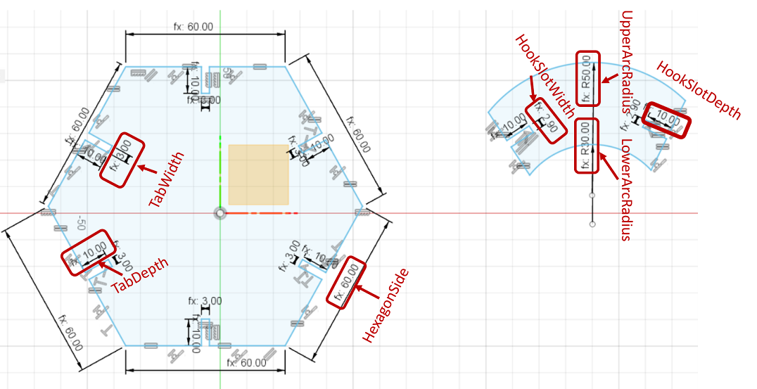
Figure 17. Defined parameters on the sketches in Fusion 360
For drawing the joint, I used Create->Arc->3-Point Arc and Recatangle to make the slots.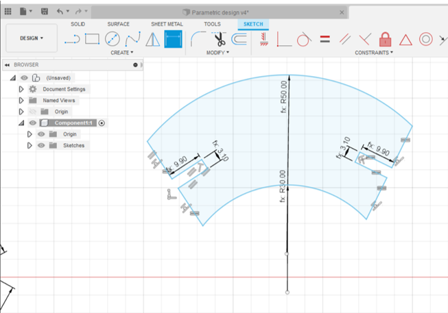
Figure 18. Drawing the joint in Fusion 360
Then, I found it would be much easier to just draw rectangles crossed the hexagon sides and then go to Sketch>>Modify>>Trim menu from panel to remove the unwanted sides. I also used Constraint panel to align or equality the lines. After finishing sketches, I extruded the object to 3mm simply by pressing E (or Go to Solid>>Create>>Extrude).
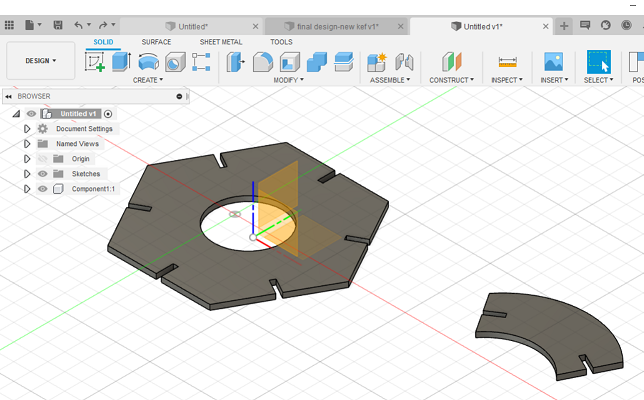
Figure 19. 3D design in Fusion 360
Now, it is the time to save your design as .dxf or directly save it as pdf file to open it in Inkspace to duplicate the components as many as you want and prepare the file for print in pdf. Here, you should check the sizes and also, scale must be 1.0.
IMPORTANT!Always check the thickness of the line through going to Fill and Stroke>>Stroke style that must be 0.02 mm. Thicker lines will not be cut in Vector mode.
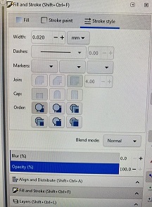
Figure 20. Setting thickness in Inkspace
Then, I saved and opened it in pdf and then, pressed Ctrl+p for printing order. From Preferences, I chose the material through going to Advanced, selected the file setting which for my case was 3mm_MDF_cut (Vector type and olny cut since there was no engraving in my design) and then pressed Load. Then, check Image Dithering to be set as Standard and click OK to send the print order.
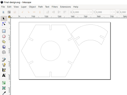
Figure 21. The test design in Inkspace
To set the lasercutter and before start printing, I did the following step:
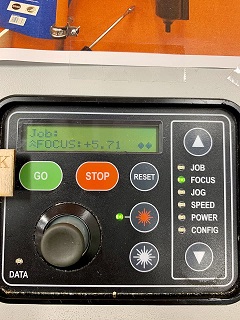
Figure 22. Control panel of the laser cutter (Epilog Fusion M2 40 Laser)
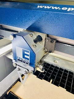
Figure 23. Setting focus point by puting the aluminum spacer
For the first try, I noticed that connection between component and the joint is quite loose, so I found that I should increase the kerf in order to have a tighter SlotWidth which I defined as (Thickness -kerf). Therefore, as Ivan guided me, I changed the kerf from 0.1 to 0.15 to see the difference. In addition, to decrease the burning around the edges, I increased the speed from 15% (as it was in the setting) to 20%. I sent it to print but this time, it was not cutting the material and I found I should decrease the speed a bit (17%). Again, I printed it and it worked!
After finding the right setting, I copied of the components several times to print a couple of number of them in order to make the desired shape and send it to pdf.
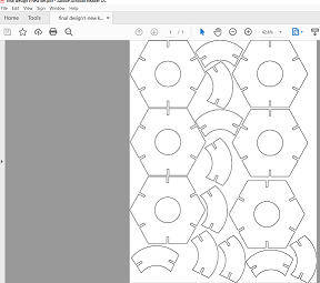
Figure 24. Final cutting design in pdf
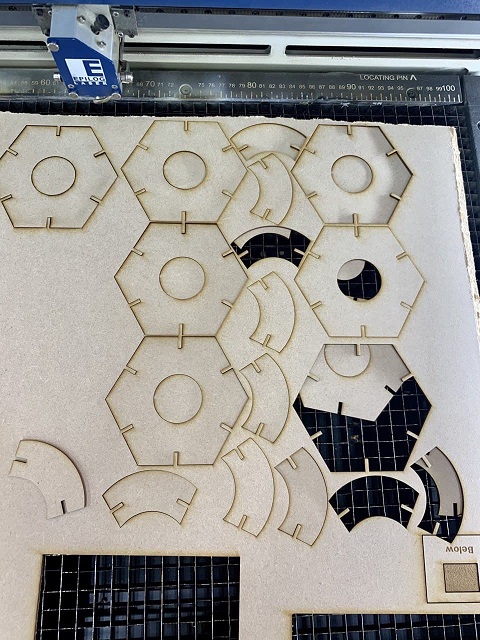
Figure 25. Cut components in the laser cutter
Finally, I connected the cut components together and after all of those challenges, this nice ball shape made although I should reconsider the size of joint to be smaller and prevent those large spaces in the product! Well, I am learning to think in 3D and this mistakes are parts of the process!:D
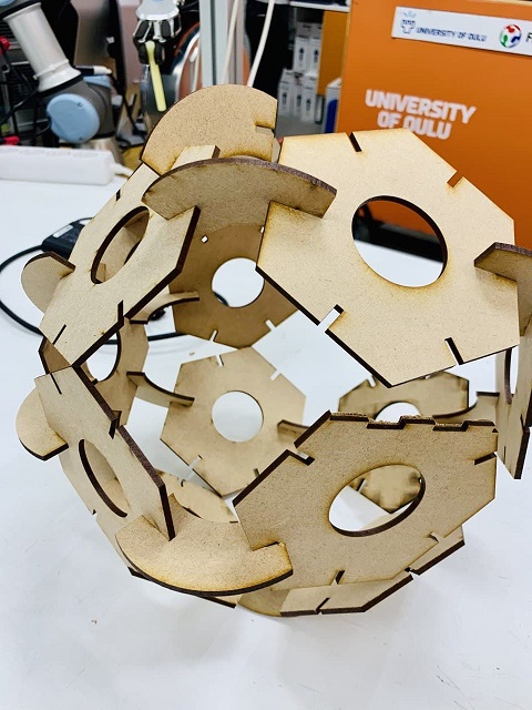
Figure 26. Final product
For documentation of this week, I have taken hints from many webpages of the former students of Fablab, especially (Arash , Gleb and Tatiana) in addition to my memory and notes from the lectures!
During this week, I got familiarized with a totally new concept as "kerf" which sounded a bit vague in the beginning to understand, but after observing the samples and measuring during the group assignment and also during my individual assignment, I understood it, completely. Then, I used Vinyl Cutter for the first time and realized that it might be better to have less thin and separated lines in the trace map to face less difficulty in the peeling process.
